V4 Chapter 31
Details
177. 2008-12-17 Rotors Running Again
After a long time of working on non-Radio Telescope stuff I now have it running again. The antenna now has the original SETI net LNA and filter ahead of the SETI Net receiver. It now runs in SETI Mode, with some software glitches, and I can move to a dual system. I should have it running in dual mode by mid-January.
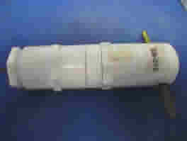
Noise Calibrator
Next step will be to build a control system for the noise generator (above)
176. 2008-11-06 Block Scan Software
I am almost to the point with the SRT antenna that I was with the Paraclipse when I was able to make the first Sun shots. The first Sun shots were made with SRT Horn and Receiver mounted at the focal point of the original Paraclipse antenna. I now have the SRT antenna (I call it the KaulTronics) up and running with the SRT Horn and Receiver.
The next step is to determine the correct focal point setting for the KaulTronics antenna. I plan to do that with a series of Sun shots starting tomorrow. As soon at the Sun is high enough I'll collect a base line shot and then move the horn in about an inch and do it again. I'll move the horn in and out by adjusting the 1/4 - 20 bolts that I use for standoffs. When I know the actual focal point of the antenna I'll move my horn and Head End Electronics to the focal point and make another series of measurements.
2008-11-09 - Sun Shots - I ran about 32 Sun Shots and used the chart and data output to debug the Bulls Eye software as I went along. The ones below came out nice to look at as well.
2008-11-10 Baseline Sun Shot
I have finally settled on the focal point of the KaulTronics dish - 48" just like the SRT papers say. I arrived at that point by running several Sun Shots while adjusting various software parameters and by moving the horn in an out. I replaced the 1 1/2" plastic standoffs with 1/4 - 20 threaded stock and a bunch of stainless nuts and washers.
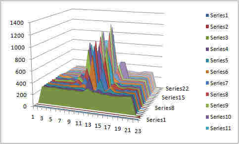
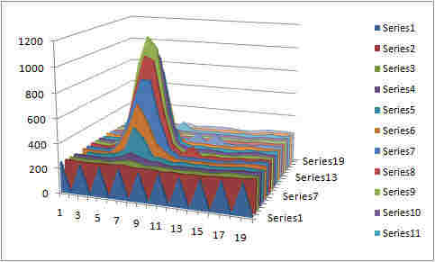
The final screen shot today (shown below) will be the baseline for all future modifications to the horn. These two charts are from the same data set - a 20 X 20 array of points created by the SETI Net Bulls Eye software and Excel
The top chart makes the nicest looking picture but the bottom one gives the most information. From that chart the Half Power Beam width (HPBW) is about 5°.
The antenna Gain is:
10 Log(P1/P0) = 8 dB
.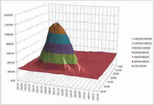
3-D Area Plot
Azimuth from 150.39° to 169.65° in 1° increments. Elevation from 39.87° to 8.82° in 1° increments. The vertical scale in in kelvin (un-calibrated)
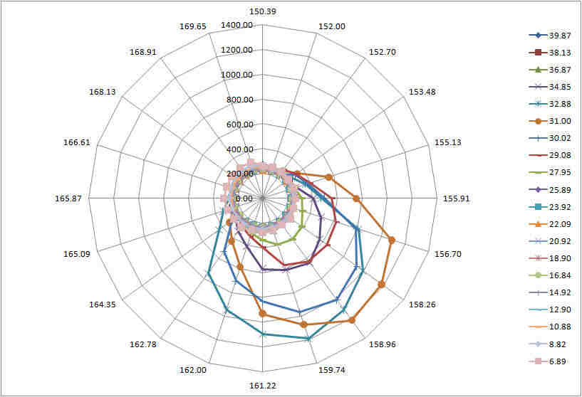
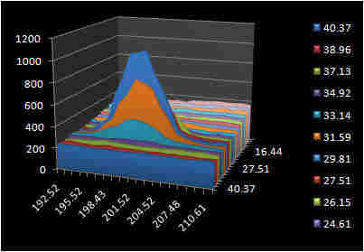
Radar Chart
Perimeter of this chart is Azimuth from 150.39° to 169.65°. Colored lines are Elevation from 6.89° to 39.87°. The amplitude is shown in concentric rings. The 31° Elevation ring shows the maximum Sun temperature (1200 kelvin).
175. 2008-10-21 Elevation Stop Switch
Now that I have a handle on the antenna software, thanks to the SNAMV (below), I need to clean up the lower limit switch on the antenna. The stock H-180 comes with a cheap pin stuck in a hole on the main gear that trips the end of travel switch and shuts down the motor. I needed a better adjustment that that (you have to bend it with a hammer) to get the elevation set correctly.
I found a thing called a 'Upper Plate' clamp at a hardware store that specializes in electrical supplies (you know circuit breakers, conduit etc) and added a solid nylon striker to make a better end of travel switch.
Clamp and trip switch
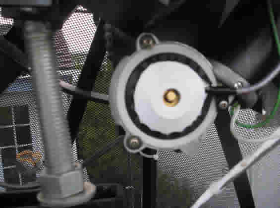
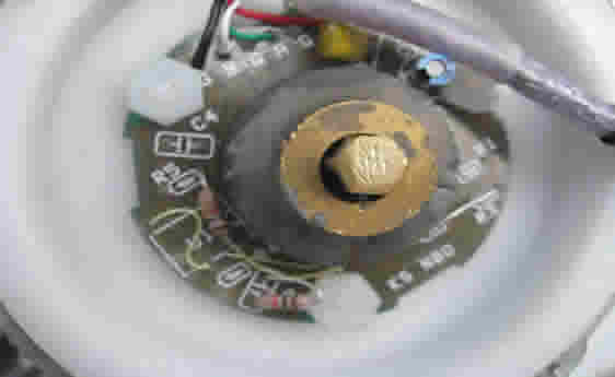
Motor Position with cover Without Cover
The motors have been modified to support the Kerr motor control modules. This includes adding a dual Hall Effect sensors rather than the single magnetic reed switch that came stock.
174. 2008-10-20 Movement Visualization Model
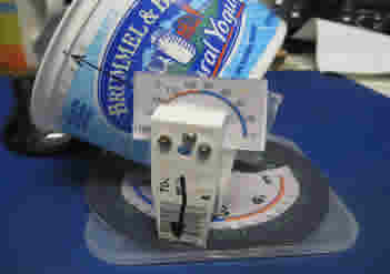
I was having trouble getting the code for the antenna movement to work and after several days of pounding on it I realized that I didn't have a good visual image of what I was trying to implement. So I built the SETI Net Antenna Movement Visualizer (SNAMV).
Az 60° El 40°
Antenna in Quadrant 2 at 60° Azimuth (North/East) and 40° elevation. The Elevation motor encoder is at 40° and the Azimuth motor encoder is at 120°
Az 300° El 50°
Antenna in Quadrant 3 at 300° Azimuth (North/West) at an elevation of 50°. The Elevation motor encoder is at 140° and the Azimuth motor encoder is at 60°
Material:
- Base Plate - Plastic CD cover
- Az Position Rose - Compas indicator Xerox
- El Position Indicator - Print of gauge (below)
- Az Gimbals - Rain gutter clip
- Dish - Brummel & Brown Yogurt cup
Feel free to copy this fine precision tool. The original will be retired to the Smithsonian.
173. 2008-10-16 Rotor Control Logic
The addition of the twin H-180 rotors has complicated the logic necessary to drive the motors. Below is the logic diagram that will be implemented.
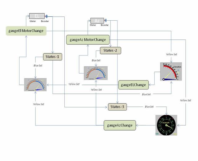
The figure is coded as followes:
- The open figures are processes.
- Yellow Needles are the Proposed position.
- Blue Needles are the results of the movement so far.
- Figures marked 'change' are entered as a result of a needle position change.
- Status is entered once a second when the antenna is active.
172. 2008-10-16 Antenna Control Software
I completed the presentation to the astronomy club last night and now can move ahead on the antenna control software. Both motors have been changed to Hall Effect dual channel sensors and seem to work fine.
The first cut of the control software looks like this:
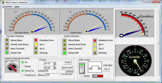
The twin motor control gauges are working and I am hooking in the Elevation and Azimuth gauge now.