V3 Chapter 26
2006-06-16 to 2006-08-12. Recalibration of the antenna Lock-To-Lock logic, addition of counter weights, Work on the status page (stalled), purchase of a spectrum analyzer and O'Scope, Construction of a audio front end device and Client/Server nears completion.
Additional Content
147 Communication Problems (2008-01-01 to present)
I am using three Kerr modules to control the antenna, one for Az, one for El and a third to switch the filter in and out.; They run on a RS-485 bus that, through a converter, is connected to my computers RS-235 port (actually a USB port configured to act like a 232 port).;; The problem I am having is that I can communicate with all three controllers until I turn on the motor power supplies and then I get a multitude of errors.
A quick email to the supplier of the control cards, Jeffery Kerr, made it clear that the earth returns on the motor power supplies must float.; I had them tied to earth through the 110 VAC cable.; After changing this things improved but I still have errors.; I ordered a now I/O board from Kerr to replace the out of date one I am using and a new SERVO SC board to replace the one that seems to be generating the errors.; These should be in sometime this week for another go at it.
146 Rotor Dead (2007-08-20 to 2007-12-31)
Well it happened again.; The rotor has been making a lot of noise as I move it in elevation but it finally quit. It can no longer lower the antenna. It can raise it, which is odd, but it cannot lower it. Today I managed to pull the antenna off the rotor and the rotor down from the mast and onto my work bench.; After opening it up its clear that the Elevation motor gearbox is trashed.; Really bad news.; I have already changed to Az motor and gear box but I was very lucky to be able to shoe horn it into position.; This motor is in even a tighter location.
It might be a while before I'm back on the air but stay tuned.
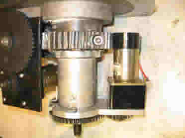
2007-08-25 I think I can squeeze a new elevation rotor motor.; When I changed out the azimuth rotor motor I bought 5 motors from EBay for the job.; Never hurts to have spares.; I didn't think I could use one of these powerful little machines for the elevation because of a clearance problem in the mount.
While thinking about the problem I may have found a solution.
 (1).jpg) Click
Click
I think I can 'tilt' the motor about 5 degrees and still have the two sets of gears mesh ok AND clear the main pinion gear for the azimuth.; I plan to shim up one side of the motor with a 4 mm nut to make it work.; Its not the best but better than nothing at all.; I have to finish drilling mounting holes in the 1/4 aluminum plate and then add an electronic position counter to the top of the motor. I know how to do that part since its the same as on the azimuth motor.; It might work.
2007-09-09 I have decided that I have to re-surface my back deck before I can install the antenna again.; This involves a lot of back breaking carpenter type work but is necessary because the wood of the deck is over twenty years old now.; At the rate I am going it may be another month before the deck is finished.; I also have received a new motor for the elevation function.; Remember the 'last gasp' attempt to replace the elevation motor was in trouble because the motor did not fit correctly.; This latest EBay purchase is a bit smaller and comes with an encoder built in so I will not have to install one myself.; The end result is that I have a much better chance of getting back on the air but it will take time.
2007-09-12 Work on the deck is proceeding with about 20% complete.; I am near the point where I can reassemble the antenna on the new portion of the deck as soon as the rotor is running again.
 New
Elevation motor
New
Elevation motor
The new motor is in place now.; It is a lot smaller than the one I had intended to use as a replacement but it seems adequate for the job.; It just barely clears the main azimuth gear which was the problem with the last motor.; It also has a much nicer gear box, the black cube, and is standard so that if it breaks again I can fix it.
Next I have to wire up the new motor, test the motor encoder (under the top black hat) and get the rotor back up the pole.
2007-09-21 I now have enough of the deck finished to re-install the rotor and antenna.; You can see the picture on the front page of this web site.; You can see two 'pipes'; the one on the left is my Jin-pole that will be used to lift the antenna and rotor; the one on the right is the 5" mounting pipe with the white adapter on top.; This is where the rotor connects.; I should be back on the air by the end of this month.
2007-09-22 It turns out that the nice little motor that I picked up from EBay for the elevation has an encoder on it alright but its a single pulse type; I need a bi-phase encoder for my electronics to work.; I do have the right kind of encoder on the old motor, the one that broke, so I guess I'll have to figure out how to extract it from the old and put it on the new.; I have done this before when I replaced the Az motor so its not an unknown operation for me.
2007-09-23 Well now I back full circle.; I can't adapt the old bi-phase encoder for the simple pulse one on the motor so I have decided to use the original, larger (in power and size) motor.; For that I have to adapt the original encoder to this motor but its the same task as for the azimuth motor so I know how to do it.; I also realized that I don't have to tilt the motor as far as I originally thought.; This is because the large azimuth gear will not grind into the motor - the motor rides around with it in a stationary position.; I can snug the motor up as tight as needed to make it work.
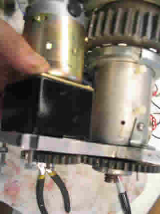 Back to the full
size motor
Back to the full
size motor
As of tonight I have the encoder mounted on the new motor and wired up.; I need a few zip ties, which I'll get from Radio Shack tomorrow, and then its on to testing theencoder.
2007-10-01 The encoder works fine and the rotor re-write is complete.; Its now on to some clean up on the Control Box that holds the positioning electronics and power supplies.; Work in progress.
2007-10-06 Still problems.; The new power supply I built is rated at +30VDC at 4 Amps but this is not enough to move the rotor, when loaded, from a dead start.; The power supply goes into current limiting and the motor cant get it going.; I think I'm going back to a simple Cap/Choke/Cap power supply that should give enough kick in the pants to get it started.; More work.
2007-10-13 Well I think that today is the day that I get it running again.; I have been trough a plethora of problems including:
- Blowing out the dual comparator op amp in the elevation motor Hall effect sensor
- Blowing out a very small 150 nF cap in the same sensor (these never go out but this one did
- Breaking the ring magnet on the azimuth Hall effect sensor.; This was a real concern but I found that you can glue things like this back together using JB Weld
- Numerous problems getting the new motor to run with the software
- Numerous problems getting the whole rig into the the cast aluminum case.
I may have it solved
2007-10-20 Or I may not have it solved.; I put the antenna back up but found that the elevation motor cannot raise the 350 lb antenna so I pulled it down and replaced the 12:1 gearbox with a 25:1.; Reassembled and the antenna moved but not without a push.; I am out of gearbox options now so I scanned the net and ordered a 100:1 but it turned out that the supplier was sold out.; More scanning and I found that Japan Servo, US distributor had some but the only choice was 300:1 so I ordered three of these.; I know that 300:1 will be very slow but that is acceptable - I don't need a huge amount of speed.; The new gearbox's should come in this week so we will see.
In the mean time I'm spending time completing the re-surfacing of my deck with 2X12" 12 long Douglas fir.; Mind numbing work.
2007-10-25 I received the three gearboxes from Japan Servo but they don't fit the motors I have so back they go.; Damn.
2007-10-29 I received four motors from an EBay auction today.; The all have small motors on them but have 200:1 gear boxes on them.; I tested one with one of my higher power motors and it seems to match up well.; I have Yet Another Motor coming in from another EBay auction Friday with a 90:1 gearbox so I think I'll wait for it to come in before pulling the antenna down again.
The deck is finished and today I'll stain it and start the trim painting.
2007-11-11 Well the last motor from EBay turned out to be to large to fit into the case so it was put aside.; I then modified one of the smaller motors of the set of four and mounted it.; After a day of working on it I got the antenna back up but the new motor still will not raise the antenna.
I am screwed.; A new motor cost over $700 and it seems like the only one that will work.; SETI Net may be dead.
2007-12-25 Or I may not be screwed.; I have the rotor back down again and have a different motor and gear case installed.; Stay tuned.
2007-12-31 It works.; I have a motor installed that will raise the antenna using the 1:120 gear case.; The trick turned out to be adding 70 lbs. of counterweight to help it along.
145 3.9 KHz Note (2007-08-10 to 2007-08-20)
Somehow a 50 Microvolt 3.9 KHz signal crept into the DRM module that I have installed in the receiver.;This note caused a false alarm while I was monitoring the WOW signal area -; I have to dig this out before I can go any further with the search.; I know its in the IF chain of the receiver or the DRM module itself because tuning off frequency does not move the note.; Stay tuned.
2007-08-15 - I have been very busy in the last few days so I haven't been able to put the attention to this problem that it deserves and because of this problem I haven't been running my SETI station at all even though Its fully automatic.; What to do?
I have decided that I will put a band aid in the software that will simply ignore the 3.9 KHz note for a while.; Its very local to bin 2896 so when ever a hit turns up in that bin I'll simply close my software eyes and move on.; This is the type of problem that can only be solved because I wrote all my own software and have complete control over it.
I should have the system running again it time to monitor the WOW area tonight.
144 Second look at antenna response (2007-07-24 to 2007-07-24)
I am looking again at the antenna scan using GPS signals at 1575.555 MHz and an elevation of 44 degrees .; This seems like a better carrier to look at.; I use using an integration time of 8 seconds on the scan below.; Eyeballing the curve it appears that the Half Power Band Width (HPBW) is 110 to 120 degree or 10 degrees.; It also seems to be shaped more like what you would see in the ARRL Antenna Handbook.
 10 degrees HPBW
Antenna is at Az 112 degrees (peak) and held at; elevation 44 degrees.
From base of about 3 mV to a maximum of 13 mV
|
I like the very top part with the side lobe on the left and (sorta) on the right.; This goes from 11 mV to 13 mV and appears to be no more than 4 degrees wide.; This makes me feel better about the operation of the antenna, horn, BPF and Line amp.
Have I tapped into the intergalactic internet (2007-07-18 to 2007-07-19)
Ok - I have your attention.; This is a serious question for anyone that wants to tackle it.; This it what happened.
I was testing the receiver stability and decided that, for a test, I would crank up the integration time much past where I usually run it.; I changed the integration from 6 seconds to 300 seconds; set the system on autopilot and let it run.; I fully expected that the result of a high integration time would be a waterfall with a bland wash of colors that matched the non-linearity of the audio system I use.; I thought this because integrations smoothes out random noise and so I assumed that the higher values would simply smooth it more.; I was wrong.
After about 1/2 hour the SETI alarm went off.; I opened the Control Panel and looked at the waterfall.; It was covered with vertical lines (click the thumbnail below).
![]()
Thumbnail with lines (400 Kb)
If you look at the left side of the picture you can see the results of bin shifting that goes on during the data collection process.; Remember I bin shift so that the earths Doppler is removed from the analysis buffer and the resulting image and therefore any vertical signal should be 'not from earth'.; Why all the vertical lines? Why are they not shifted with the left side?
One answer could be:
|
This is, of course my preferred answer but probable not correct.; What causes these lines?; Here is what I know:
1. The Integration Algorithm (simplified).
;FFT.Transform; // Do the FFT
for i := 1 to (FFT.SpectrumSize div 2) do //; Do the Integration and Draw
begin
;; bufIntegrate[i - 1 + BinShift] := (FIIRa * FFT.Magnitude[i]) + ((1
- FIIRa) * bufIntegrate[i - 1 + BinShift]);
end;
frmWaterfall.DrawLine(bufIntegrate {, FFT.SpectrumSize div 2});/ /; Send
the FFT to the Waterfall
2. the bufIntegrate (the integrated buffer) is the what each horizontal line on the jpg is created with and what is tested for signals when a full frame is complete.; The term FIIRa is the integration value I use and was set to 300.
3. I don't see the mass of vertical lines until I move the integration time (FIIRa) up to about 20.; Then they start to appear.
4. The detection algorithm finds these lines and sets off the alarm when the amplitude in any one bin is about 8% higher than the amplitude in the surrounding 10 bins.
Any idea for me to work on?
142 TestingReceiver Stability (2007-07-11 to Present )
I use a Digital Radio Mondale (DRM) module to shift the 455 KHz receiver IF down to the audio range.; This gives me about 18 KHz bandwidth that I can send to the FFT. A quick look at the data sheet and the DRM module shows that it is a;free running oscillator.; The data sheet also shows an example;application with a xtal which should help a lot if the DRM is a problem.
I set my receiver to the frequency of the Weak Signal Source and watched it create the following waterfall
![]()
It shows itself to be wobbling around short term.; A full waterfall takes about 20 minutes to complete at 1.34 Hz/Bin and the WSS jerks around 3 or 4 bins once in a while (click on the jpg thumbnail above) but seems to end up almost in the same bin as it started in every time.; The trouble is that a perfect ET signal that had just the right amount of Doppler on it to produce a vertical line in my chirped waterfall would not sound the alarm if the system drifts around four to five bins during collection.
2007-07-12 I have added a BNC tap on the WSS at the 118 MHz point and now have the WSS warming up.; I'll let it run until tomorrow, when it should be about as stable as its going to get, and then start the measurement of the receiver stability.
2007-07-13 The WSS has run all night and appears to be stable.; The HP 5316B counter moves in short term (2-3 seconds) jumps from 118,365,034 Hz; to 118,365,036 Hz.; This 3 Hz change will result in 2.6 Bin shift at maximum resolution and could account for the short term jitter I see on the waterfall.
When I turned on the receiver and ran the waterfall on it this is what appeared:
 Thumbnail at 8:30 AM
It appears that, during warm up, the receiver drifts about 300 bin in the 20 minutes it took to create this waterfall. That's about 1500 Hz per hour and much too high.; I'll watch it to see how long before it stabilizes.
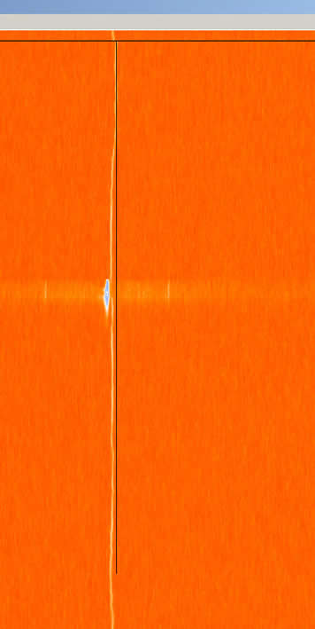
After an hour and a half the receiver seems to have stabilized.; The thumbnail below shows the receiver drifting about 8 bins (10 Hz) over a 20 minute period and short term and 15 Bins (20 Hz) over about 5 minutes.; The 'blidget' in the middle of the screen is me switching the WSS to high power for a short test.
Thumbnail at 10 AM
Bottom line is that the receiver is useless until it has warmed up for several hours and then its not useable at the highest resolution.; I now need to isolate the DRM module drift from the receiver drift to see which is at fault.
I can send the normal, non-DRM audio, to the waterfall to see how the receiver by itself drifts.; Stay tuned.
The thumbnail below is directly from the audio of the R7000 running in the SSB mode
 Receiver without the DRM module
It looks like the problem is in the receiver not the DRM module.
Now what boss?
141 Antenna Testing (2007-06-06 to 2007-06-10 )
I am considering better ways to calibrate the antenna and horn.; One of these is to resurrect the Weak Signal Source (WSS) and hang it on the flag pole.; Its inside the near field of the antenna but might be better than nothing. ; I'm going to do it. X
This test was a complete bust.; The signal is so near the antenna and so low that there is now way I could ever do a raster scan on it.
1007-06-13 I did try looking at the L1 GPS frequency 1227,600,000 and it makes a much better signal source. I also had to shut off the LNAs band pass filter.
This is the raster scan.
Antenna is at Az 119 degrees (peak) and held at; elevation 48 degrees.
From base of about 1 mV to a maximum of 5 mV
|
This agrees with what I expected, considering that the LNA and horn are both out of band, and does show the crummy hump on the right side of the chart. At least this is something I can baseline against;