V3 Chapter 25
2006-06-16 to 2006-08-12. Recalibration of the antenna Lock-To-Lock logic, addition of counter weights, Work on the status page (stalled), purchase of a spectrum analyzer and O'Scope, Construction of a audio front end device and Client/Server nears completion.
Additional Content
140 Antenna Dimensions (2007-05-24 to Present )
From the previous entry (below) you can see that I'm having trouble with my antenna and possibly the feed horn. This is one of those things that doesn't become apparent until you do a close in look at your equipment. That's what happened when I built the Raster Scan software and turned it loose on my system - I found problems.
Ed Cole suggested that I re-look at the way the antenna system is constructed and I agree. Its has to be a mechanical problem. My old college professor once. told us that "All problems are mechanical. Never in the history of the earth has an electron failed to go where it was suppose to").
With that in mind here are the dimensions.
Antenna (Paraclipse 12 foot)
| Parameter | Reference |
| Reflector Diameter 3.7 Meters (12.1 foot) | Mfg spec |
| Focal Length/Diameter Ratio .375 | Mfg spec |
| Focal Length 1.36 Meters (4.53 foot or 54.36") | calculated |
| Reflector Depth 0.63 Meters (2.1 foot) | ? |
| Feed illumination angle 137 degrees | League spread sheet |
| Illumination Efficiency 55% | assumed |
| HPBW 3.37 degrees | League spread sheet |
| Minimum Drift Scan time 807.9 seconds | League spread sheet |
Horn (RAS)
| Parameter | Reference | Measured |
| Waveguide Diameter 6 inches | 6" | |
| Lower cutoff 1.14 GHz | League spread sheet | |
| Upper cutoff 1.49 GHz | League spread sheet | |
| Guide Wavelength 35.2 cm | League spread sheet | |
| Probe placement 3.47 Inches from back of horn | League spread sheet | measured 3.5" |
| feed horn length 10.41 inches | League spread sheet | measured 11" |
| Choke ring Depth 4.16 inches | League spread sheet | measured 4.1" |
| Choke ring diameter 14.32 inches | League spread sheet | |
| Feed horn Lip placement (Focal Length less 1.46 Inches) | League spread sheet | Measured 50.5" |
| Choke Ring placement (from front of feed horn to back of choke) 4.59 In to 4.10 in | League spread sheet | Measured 5" |
LNA (RAS)
| Parameter | Reference |
| 28 dB gain | Mfg spec |
| 0.37 NF (26 degrees) | Mfg spec |
Band Pass Filter
| Parameter |
| Freq 1375 MHz to 1450 MHz |
| Insertion Loss 0.7 dB |
139 Antenna Characterization (2007-05-22 to 2007-05-24 )
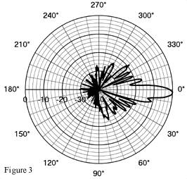
I would like to see what the antenna gain pattern looks like. I have all the tools (I think). I can move the antenna in a raster pattern. I can collect the maximum signal after the FFT and after integration and I can present the results in chart format. The results shows the decided drop in amplitude at about 175 degrees Az. No idea why.
This signal peaks at 185 degrees Az and is located at 40 degrees El. It is found, in my location at 1424,560,000 Hz. I was running at 5.1 seconds integration.
The maximum signal was 18.1 mV at 161.31 degrees Az and the minimum looks like 4 mV (from the chart). The gain of the antenna is:
dB = 20 log(E1/E2) = 20 log(18.1 / 4) = 13.1dB
This is much lower than the gain calculated from the dimensions of the antenna itself (32 dBi ) and much broader. The half power point looks to be about 40 degrees where it should be 3.37 degrees.
WAHHHhhh...
I need to find a signal that is clearly in the far field of the antenna. That may be the problem.
The GPS signals are all very loud and would make good targets except that they are right at the extremes of my antenna movement, so I can't raster scan past them. I did find a nice carrier at 1669,098,700 Hz at 220 deg Az and 50 deg El that seems to work OK. I'm collecting data on it now with 10 seconds of integration.
 PASS
1
PASS
1
This is the result of the scan. I'll make another pass for consistency.
PASS 2
I looked up the Specs on the horn (from RAS) and the calculations I made on it using the SETI League's spreadsheet and it came up with:
- Lower Cutoff - 1.14 GHz
- Upper Cutoff - 1.49 GHz
So I guess that could account for the very long slope on both sides of the peak and the otherwise crummy look of it.
This signal is at 1375,989,100 Hz, Az160, El 50 degrees. Its within my band pass filter and horn but I have no idea where it really is.
It does show a notch in the peak that seems to be on all the other in-band scans.
I still need to find some sort of signal within my band pass filter (1375 MHz to 1450 MHz), within the movement limits of my rotor and high enough (but not too high) to eliminate ground effects
. 2007-05-23
This is the GPS signal today at 2 Pm. Looks better but still a huge notch.
I get about 14 dB gain on this curve but its still about 15 degrees wide.
138 Hits Database (2007-05-16 to 2007-05-22 )
I am not being very disciplined in my data collection. The trouble is with 12 million places to look its hard not to say 'well this place is just as good as any other' and start listening there. What happens is that I start finding the same signal more than once and sending alarm emails for the same signal a second time. I need some self imposed discipline.
So I wrote a database module that will automatically be updated each time a new hit comes into the system. Since I can order the database columns by frequency or Dec/Ra or Az/El I can see when I'm looking where I have been looking before.
The database uses a comma delimited text file rather than full blown SQL database only because I think a simple job, like this one, is quickly overwhelmed by a massive database engine. So far there is only one entry in the database (last nights hit) but when it get to some substantial size I'll find a way to automatically post it on the web site.
2007-05-22 I have the database working now with a few of the fine points remaining to fix. One is that the DateTime saved in the file does not sort correctly for some reason.
137 How Chirping Works (2007-05-07 to 2007-05-07 )
I don't understand. You say "no Doppler", but you also say: Chirp: -0.1335 Hz/Sec. Doesn't the existence of a "chirp" signify a Doppler shift?
List Answer
Good question Daniel.The logic is a little obtuse but here it is.When I'm looking at a specific point in the sky I see all kinds of lines caused by signals. Most of these lines are from local interference and some are from satellites going overhead. The local signals create lines that run straight top to bottom in the waterfall display (the jpg). The satellite signals may produce straight lines if the satellite is stationary and in the Clark belt or it may have Doppler, and cause a line that is not straight up and down, if it is moving toward my antenna or away from it. Of course these signals are not what I'm interested in.I'm looking for signals that produce lines that move to the left in the jpg, lower in frequency. How fast they move to the left is very important because if they are from an ET they will move at a rate caused by the earths rotation. That's key. Since we know exactly how fast the earth is rotating (360 degrees in 24 hrs) we know how fast the ET signal should move down in frequency. How to make these 'ET signals' stand out against the background of all the other signals. That's the question.What I do is to 'chirp' my receiver down frequency at the same rate as the Doppler expected from the earths rotation. The end result is that a signal from ET will be vertical and all the rest will move either to the left (faster than the earths Doppler) or to the right (slower than the earths Doppler).My detection system sums all the signals in each vertical column (Bin) and averages them It then examines each average to see if it is larger than its nearest 5 neighbors. If it is it rings the alarm and sends you an email.When the alarm goes off I step in and increase the resolution of my system so that I can see smaller changes in the line that caused the alarm to go off.So the 'Chirp' is how much I'm changing my receiver and when I say 'No Doppler" it means that the signal under investigation is not staying in its bins enough to trip the alarm at higher resolution. I guess I really should say "Not the right amount of Doppler".
I keep track of the needed chirp and when it exceeds the width of one bin (1.34Hz wide at the maximum resolution) I bin shift UP one position which has the effect of moving the signal DOWN one bin in the waterfall. When the needed chirp finally exceeds 100 Hz my software then changes the receiver down one click, resets the bin shift and starts all over again.
With this system in place a signal that matches the earth caused Doppler and manages not to wobble around more than 1.34 Hz during the creation of one jpg will sound the alarm. This has never happened yet. Lots of alarms at 10 Hz/Bin but none at 1.3 Hz/Bin.
Its not perfect but it does seem to work.
136 Raster Scan (2007-05-04 to Present)
I have decided that I want to characterize the antenna and horn better. What I would like to do is build a utility that will command the antenna Az/El to make a raster sweep over a known signal. This is a thinking out loud list of stuff I want it to do.
- Select a receiver frequency - This is easy to do so I'll incorporate the R7000 application in it. The frequency choice itself is a problem. I can generate a signal using my Weak Signal Source but I can't get the WSS in the far field of the antenna so any pattern generated would be distorted. I need to find a good frequency that has a stable, far field, signal within the pass band of my Band Pass Filter (1375 to 1450 mHz)
- Enter the top elevation and most easterly azimuth. Enter the bottom elevation and the most westerly azimuth. This will define the raster.
- Move the antenna to the start of the raster.
- Start the audio and FFT running and pick up the maximum signal directly from the FFT. I think I can do that.
- Save the data as a triplet (Az, El, Amplitude).
- Use a Excel client module to load an Excel table or find a way to use the Chart system that I have in Delphi.
- At the end of the run present the data as a 3-D chart and as a typical Font to Back ratio
 Example of Front to Back ratio Smith Chart
The trouble with a Smith chart is that I would need to measure the rear of the antenna as well but there is no way I could point the rear of the antenna at a signal in the sky (it would have to point down).
 Simple plot might work for me.
I guess I'll have to work with a simple X,Y plot for this.
135 Odds and Ends (2007-04-26 to 2007-05-04 )
Another software to do list:
- Image of Spectrum Analyzer - It would be neat to send an image of the current SpecAna to the web site. Of course it wouldn't be real time but it would give an indication of the operation. DONE. You can now see a capture of the SpecAna on the web site.
- Image of Sky Map - If I can do the SpecAna why not the Sky Map? - Done. You can now see the Sky Map with the current antenna and star
- Bird List - Fix the home directory problem on this function and check the logic. - FIxed
- Connect on Video Image - The antenna image sent to the web server is not being connected correctly. The example code manages it - why can't I? - DONE. Needed a popup menu to select the video source.
- Continuous Recording - Consider the possibility of continuously recording the WAV and jpg data. This will alow the case when a signal appears in a high resolution jpg but goes away before the end of the frame. As it is now recording doesn't start until the next frame. This would burden the processor but might be worth it.
- Yank Receiver - When the alarm goes off the receiver frequency should be adjusted (yanked) so that the signal is in the lower half of the waterfall. This will make analysis easer.
-
Questions - Comments eMail Me - I will respond..
Alert - I need to finalize the ability to automatically send email to the Argus Hits list when the ET Detector goes off. I need to find a way to attach to the Outlook Express OLE server or some other way to automate the process.- Done. I had to write a email client from scratch but it works fine now. Automatic emails are sent to the Seti Net List on every alarm. - Thread Image - Right now the process of sending the image for status and antenna halts the spectrum analyzer. This code needs to be moved to a thread. - DONE (simple dimple)
134 ET Detection System Running (2007-03-17 to 2007-03-26)
I finally have the chirp and alarm system smoothed out now. Here is how it works.
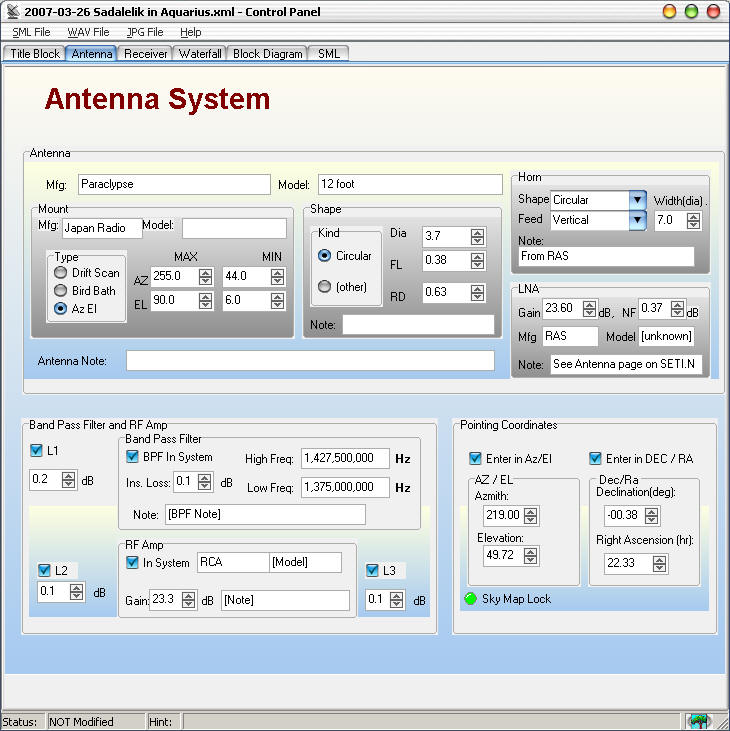
- I select the star position on the Sky Map that I want search and move the antenna to that point and lock it This thumbnail shows the antenna locked on Sadalmelik in Aquarius The antenna will stay at this DEC/Ra as long as it can stay within the horseshoe search area.
Sadalmelik

- Select the operating frequency and set it. I am going to set it at 1,420,221,100 Hz and run it in the DRM mode.
Receiver Set up

- I then set up the File Manager to keep track of pointing angles, time, frequency and all the other important parameters for the search.
File
Manager Setup

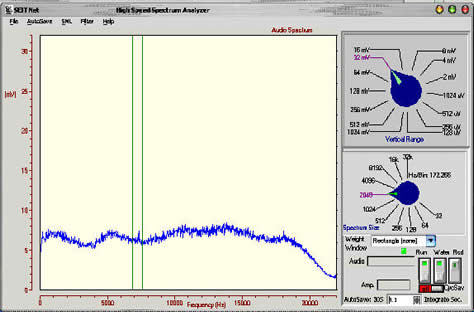
- I turn on the Spectrum Analyzer and set it for a medium spectrum size (4096) and start the Waterfall running with a 3.1 second integration period.
SpecAna with 3 sec integration
Waterfall with no sign of ET yet

- I then turn on the alarm system and the chirp calculator. The antenna image and the system status will be updated on the web page.
Control Panel with system running
- From this point on each complete waterfall (I call them frames) will be analyzed at its completion. The average of each column of bins is calculated and then each column is examined individually. Starting from the left (bin 0 + segment size) the column average is tested to see if it has more than 20% of the energy of the surrounding 11 columns. The 20% criteria (0.20 on the display) seems to generate the least false alarms. Eleven is the segment size selected on the waterfall. If none of the columns meet this 20% criteria the process starts over with a new waterfall.
- If a signal come into view it will be recorded on the waterfall as a line that moves down the waterfall.
- If the signal is local ( there are lots of these), it will appear on the waterfall to move DOWN in frequency. This is because the waterfall is being shifted right by the calculated chirp (the Doppler shift caused by the earths rotation). Since a non-ET signal will move from column to column during each waterfall it will not set off the alarm.
- If it is a signal 'not from terra' (extraterrestrial) it will form a line straight down the waterfall because the columns are shifted by the same amount. If it manages to stay within one column position it will trip the alarm.
- If a column does reach the '20% greater than its neighbors' criteria the green LED will be set on the waterfall, the green LED on the control panel will change to red and a loud 'ET Song' will be played to shake me out of bed. The system will switch to record and the raw PCM data will be captured along with each frame in the form of a jpg. If the system is in one of the scan modes it will stop scanning and concentrate on this antenna position and frequency. Each WAV and jpg file will also contain all the data in the File Manager to later identify the exact setup when the alarm went off.
- If the candidate ET signal goes away the Waterfall LED will shut off but the system will continue to record until the alarm is manually reset.
- On an alarm I will take over control of the system perform several verification steps. I will move the antenna off axis by three degrees in both Az and El. An ET signal should disappear. I will also shut down other local signal sources that I have control over, such as my Weak Signal Source beacon, to see if the signal is an image of one of these. I will also switch the band pass filter in and out of the system to verify that the signal is not an out of band image.
- I will then increase the spectrum size up to the maximum to shrink the bin size. This will make the Doppler shift more pronounced. At 32 K it is about 1.3 Hz/bin.
- If the candidate passes all of these tests I will notify the SETI League HITS list and continue to monitor. I will also notify my bank to expect fame and fortune.
133 TO DO List (2007-03-17 to 2007-03-17)
- Update the description of the integrations system showing the better operation running now
- Incorporate the antenna image into the scanning system and fix the video connect operation
- Make decisions on the details of the detection protocol.
- What should be saved
- Should the antenna be moved - left/right, Up/Down, circular scan, raster scan - what
- Should the receiver be pulled to the bin reporting the hit
- How to turn off the alarm - Should it stay set until I manually reset it?
- Work bird list into scan option
- Rebuild SpecAna record function for external control
This screen capture is of a test signal injected into the audio output of the receiver. The small 'pip' between the two green lines is a Hit. I used the green cursors to highlight the position of the hit.
The waterfall of this signal shows a barely discernable blue line at bin 339 which is the pip
 Waterfall Thumbnail
As you can see from the status line at the top of the waterfall this signal segment size is 7. So the bin with the signal is 15% larger than the seven bins below and the seven bins above it. When the first hit is detected any other matches in that frame are ignored.