V2 Chapter 12
More work on the software and release of the OLE Clock Server, Spectrum Analyzer and theSML Generator. Addition of counter weights to the antenna, Azimuth limit switch installation, a new line amplifier and the presentation of the schematic of the LNA and filter system. Also the repair (again) of a jammed rotor.
Additional Content
61. Work on SETI Software (2005-02-06 to 2005-03-18
- 2005-03-18 Release all modules (Clock, SML and Spectrum Analyzer,) again and move on.
- 2005-02-26 Modified the Spectrum Analyzer. Added a tone generator from David Taylor.
- 2005-02-25 Modified the SETI Net Clock (OLE server) to clean up some minor errors.
- 2005-02-15 - The Hardware System Block Diagram was corrected and is now presented as a normal web page. This will make it easer to read and will not require a download.
- 2005-02-14 - Corrected spelling on interface Was AntennEl is AntennaEl (version 3.0.5)
Now that I have the SETI Net Clock running as an OLE server I decided to change the main SETI Software to make use of it. Previously it simply called the clock code inline as a Delphi unit but I have found that calling the software as the end users normally would call it makes the whole system much smother. When I find a bug the users immediately have access to the fix.
Delphi Type Library for the SETI Net Clock Server |
| SETINetClockServer = ISETINetClockServer; // *********************************************************************// // Interface: ISETINetClockServer // Flags: (4416) Dual OleAutomation Dispatchable // GUID: {C9B22FFC-476A-40BB-A914-6461C5DECEFB} // *********************************************************************// ISETINetClockServer = interface(IDispatch) ['{C9B22FFC-476A-40BB-A914-6461C5DECEFB}'] function Get_StarAz: Single; safecall; procedure Set_StarAz(Value: Single); safecall; function Get_StarEl: Single; safecall; procedure Set_StarEl(Value: Single); safecall; function Get_AzMax: Single; safecall; procedure Set_AzMax(Value: Single); safecall; function Get_AzMin: Single; safecall; procedure Set_AzMin(Value: Single); safecall; function Get_ElMax: Single; safecall; procedure Set_ElMax(Value: Single); safecall; function Get_ElMin: Single; safecall; procedure Set_ElMin(Value: Single); safecall; function Get_Version: WideString; safecall; function Get_AntennaAz: Single; safecall; procedure Set_AntennaAz(Value: Single); safecall; function Get_AntennEl: Single; safecall; procedure Set_AntennEl(Value: Single); safecall; property StarAz: Single read Get_StarAz write Set_StarAz; |
To make use of the Clock Server I needed to expose more functions and methods. The latest version of the clock has the following methods:
These properties can be accessed in the new version of the clock the same way the original ones (StarAz and StarEl) were used. See the engineering note book for an example of a Visual Basic.net client that makes use of the clock.
60. Antenna Counterbalance (2005-02-04 to 2005-02-05)
The elevation rotor can no longer raise the antenna. It was always a bit on the underpowered side but not it simply fails about 1/2 way up with a position error exception. I have played with the servo control parameters all day and cannot make it work right. It works find in the direct drive mode (where the DC is simply applied to the motors) but in the Pulse Width Modulation mode it troughs a position error event and quits.
I have decided that what it needs is a counterbalance. After much searching on web - not much help, and several calls to other Argus members via the list I was able to get a picture of a commercial counter weight for this antenna from Dr. Paul Shuch. He uses the same antenna but a different mounting system than I do.
I have fashioned a test jig to see how much weight I need:
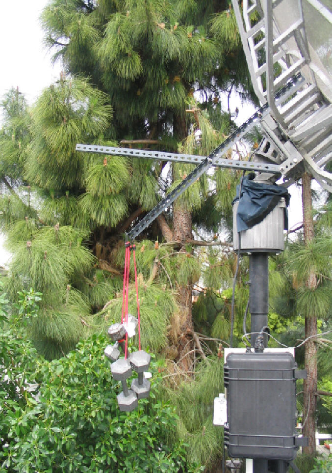 Test Jig - 64 lbs on a 36" arm
This setup has 64 pounds hanging on bungee cords and a lever arm of 36". With this amount of weight the antenna moves up and down without failure. It also works with 44 lbs on it so somewhere in this range seems about right.
I have the counterweight finished now. The picture below shows the full upright position:
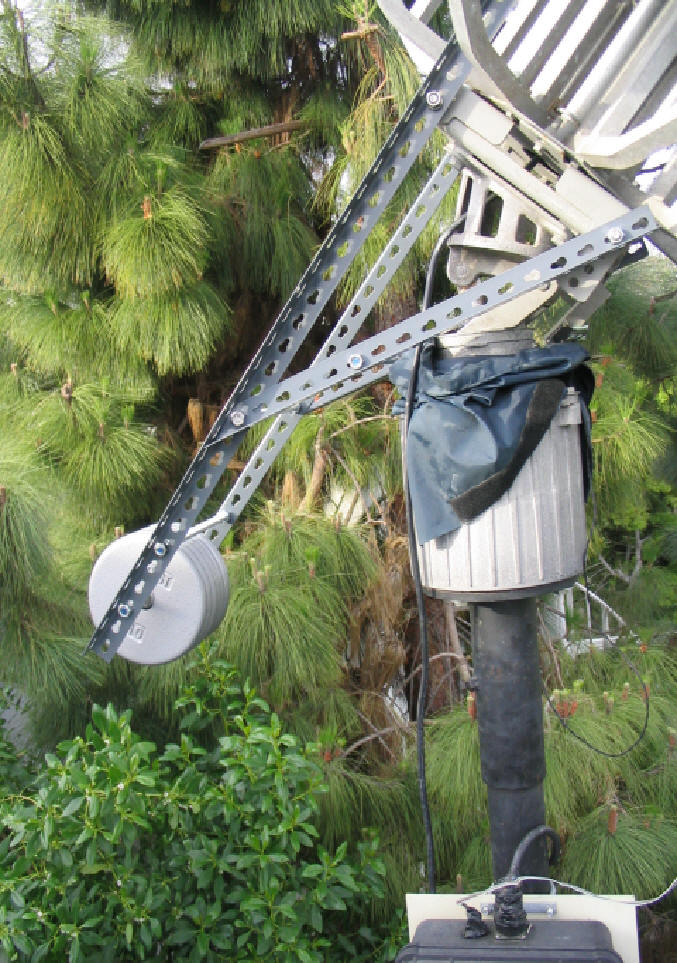 Completed counterweight
I used 1/2" stainless nuts and bolts and 6 - 10 lb weights from the local muscle building supply store.
Task Complete
59. Azimuth Limit Switch (2005-02-03 to 2005-02-04)
After all the problems with the rotor system now that I have it back together and up on the pole - the azimuth limit switch doesn't work anymore. this could be a loose connector inside the rotor or a broken wire in the control box. If its a loose connector I'll build an external limit switch and bring the wires into the control box the way I did when the elevation limit switch quit working. If its a wire inside the control box it should be able to be fixed without to much trouble.
2005-02-04 It turned out that a couple of things were bad. First I found a cold solder joint in the power to the LEDs, second I had a 7406 in the relay logic when I wanted a 7405 open collector driver. Third I had to add a 2.2k pull up resistor to the limit switch lines. I have no idea how this ever worked except that maybe the 7406 has a pull up on its input line and lastly I put a LM7412 three terminal regulator and a 4.7 uFd cap in front of the LM7405 that was powering the logic. The LM7405 was getting very hot with 15 volts of headroom.
After all this the antenna logic seems to work correctly. Now I have to figure out why the elevation motor cannot lift the antenna like it should.
58. Horn and LNA investigation (2005-01-31 to 2005-03-01).
Since the antenna is down for the rotor fix (item 57) I decided to take a look at the physical horn dimensions particularly the probe placement and check out the operation of the LNA, filter and line amplifier. I verified all the dimensions that were calculated several years ago and then turned my attention to the filter switch and line amplifier.
Mounted on the back of the horn is a weatherproof box that houses the LNA, Filter and line amplifier. The circuit is shown below.

From the schematic you can see that I can switch the filter in or out of the circuit from the control room
There has always been a problem with this system. When the filter is in the circuit (Xfer Relay in its normal position) everything works fine. I did notice a little instability so I put a 3 dB pad in the input side of the MAR Amp line amplifier. This cleaned it up. The problem came when I switched the filter out of the circuit. The noise from the receiver increased as expected but any signal that I was monitoring disappeared. When the filter was back in the system the signal re-appeared.
I really didn't know why the amplifier should act like that but since everything else seemed ok I decided to replace it. The line amplifier was something that I built from three MAR 6 amplifiers but I decided to replace it with a 15 dB line amplifier that covers the waterhole up to 2050 MHz. This came Radio Shack for $11.
| This amplifier has the following markings on it:
RCA D903 Line Amplifier Maximum output 950 - 2050 MHz 110 dBuV Gain 13-18 dB 25 - 40 ma |
This little device is meant to provide extra gain for TVRO or satellite systems but it has several things about it that I needed to change. First is that it picks up its supply voltage directly from the co-ax. I don't use this method on my system so that had to change. Second is that it has 'F' type connectors on it. I use SMA in most of the antenna so I wanted to change that as well.
First thing need was to pry off the top and bottom covers to get at the electronics. Then you need to cut out the voltage tap resistors found right next to the input and output 'F' connectors on the amplifier. These are about 1/8" square and, on mine at least, black. Next you drill a small hole in the side of the case so that a feed through can be mounted to bring in power. Then you pull out your trusty hacksaw and cut off both of the 'F' connectors. In this amplifier they are molded into the case and can't simply be unscrewed.
Connect the feed through to the trace that powers the internal 9 Volt three terminal regulator and then install SMA bulkhead connectors in the holes left from cutting out the 'F' connectors.
Needless to say taking a hacksaw and a power drill to a piece of delicate electronics gear is not for the faint of heart but with care it can be done - I managed. Besides the most you are out is $11 if you run the drill through the circuit board.
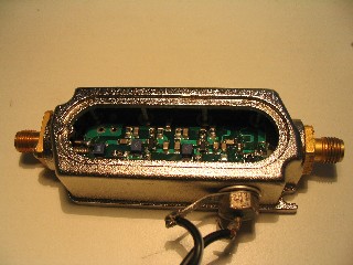 Finished Line Amplifier
 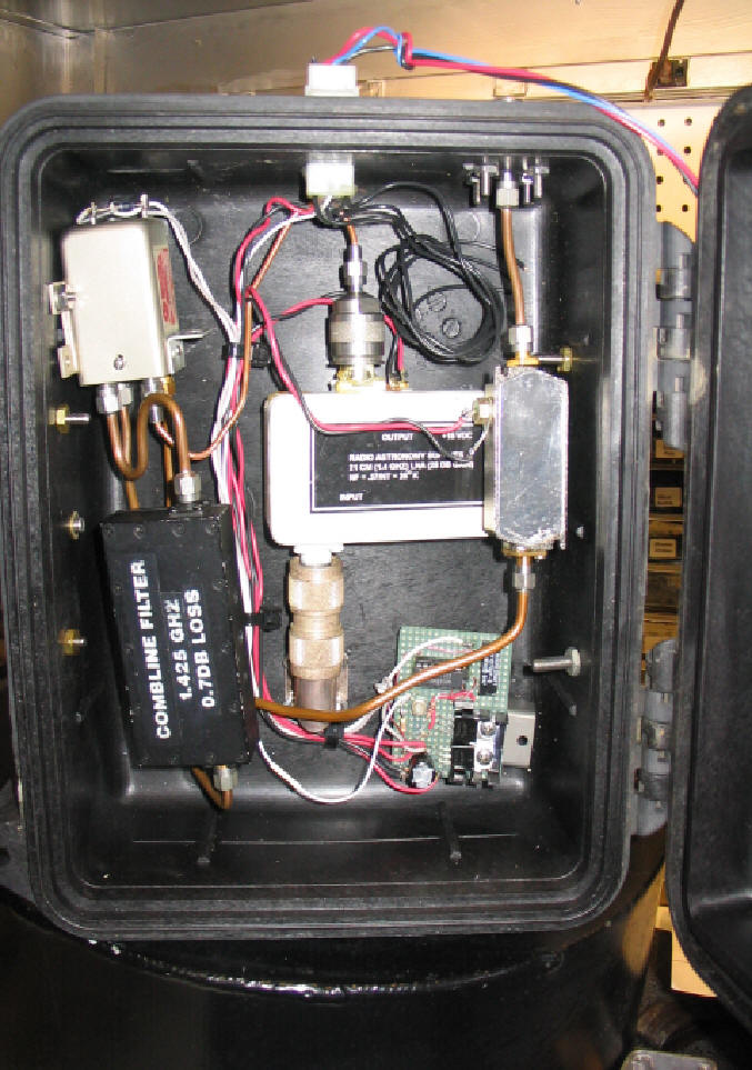 Installed in waterproof box
After testing to verify that the amplifier works correctly both with and without the filter the new line amplifier was reinstalled in the weatherproof box ready to go back on the prime focus of the antenna.
57.Antenna Rotor Problem (2005-01-27 to 2005-01-31).
For some reason I can't bring the elevation rotor up to the place indicated on the computer dial. I get Task Done before it actually gets done. It sounds like a software bug. Stay tuned.
I replaced both blinking LEDs in the control box because they were not working. They work now but the old LEDs also work so I don't really know what I fixed. That kind of thing usually comes back to life somehow.
I still have the 'Task Done' problem but while working with it I managed to get the antenna stuck in the full up position. It could be due to one of two problems:
- Jammed -The elevation piston is jammed and will require the antenna to be removed and the rotor taken down. This is a disaster since its getting to the point where I can't physically and safely remove the antenna from the rotor.
- Fuse - When I drove the antenna to full up I came to the end of the piston travel and blew a fuse. Simple problem, simple fix
Stay tuned.
And the answer is: JAMMED (damn)
2005-01-30 After much grunting and swearing I managed to get the antenna off the rotor and the rotor off the pole (I'm gett'n to old for this shit). Now I have to open it up and see what the damage is.
2005-01-31 The problem turned out to be a sheared shear pin - it did its job and broke off when I crashed into the full up position. I fixed that the tightened up all the other gears on both axis motors. I put the rotor back on the pole, using a boat winch, and then pulled the antenna to the top of the rotor using the same winch. I use a gin pole constructed for this purpose.
The Az/El system seems to work fine now.