V5 Chapter 37
Details
207. 2010-06-21 Head End Electronics Test
I decided to pull down the head end and make sure it was running right using the noise generator and spectrum analyzer. This shouldn't take too long but the system is down in the meantime.
I screwed the choke ring to the horn rather than using an adjustable strap and remounted the enclosure on the back of the horn. Mechanically its a lot better now.
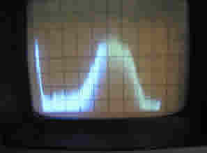
Water Hole without and with the noise source 50 MHz/div, 10 dB/div |
 |
Seems to be working fine now.
206. 2010-06-21 Noise Noise Noise
I ordered a second noise generator I saw in EBay. Its a Noise/Com NC1124A.
It has more ENR than the one I now have and still covers the band I'm interested in. At $150 it seemed like a good buy.
205. 2010-06-20 More Excess Noise Ratio (ENR) Needed
The mc50018 noise source I am using has a ENR of 25 dB but that is not enough for some of the tests I want to do. I am working on a small amplifier that runs after the noise source to get it up a bit.

Not This - This one is not
working out too well. It used three MAR-6 amps but for some reason
draws way to much current and is instable. It does put out the
kind of power I need so I need to find a better amplifier.  class="scalable fancy"
The pix on the left shows the noise source 'draped' out of the center of the dish for a test. The pix below shows the water hole (1375-1450 MHz) after going through the horn, LNA, BPF, Line amp and the co-ax run to my shack. The spike right in the middle of the screen is the Weak Signal Source beacon also in my shack. I have no idea what that *very* large spike farther up band is. The very right edge is 1500 MHz which is the limit of the HP Spectrum Analyzer I'm using.

Commercial Amp - I think I will try a commercial line amplifier. I can cut one up, put SMA connectors on it and get rid of the power feed that comes up the co-ax normally. Click on the thumbnail (left) to see what is going on. The original Line Amp case (Fry's $15) is on top and the amplifier itself after being extracted is in one of my salvaged cases on the bottom. As you can see the original case had 'stands' that the pc board was mounted on. I had to drill them out to get to the board. Then the DC feed was removed (resister with a choke coil wound around it) from both the input and the output and the power to theboard attached to a co-ax capacitor on the left edge.
Now the problem is to remount the pc board with some sort of firm grounding method. I don't know how I'll do it yet.
Well - That didn't work out so well. I mounted it in the case and attached the SMA connectors, fired it up and boy did it look crappy. Lots of spikes all over the place and putting the lid on it only made it worse. I have no idea why but this isn't the answer. I wish I would have tested it before I tore into it so that I would know if I caused the spikes or they were there all along. Live and learn.
Looks good though.

Bad Boy of the Amplifier World
To make sure I didn't have some other problem going on I sent the noise source through a HP bench top amplifier (1-26 GHz, 20 dB) and then into the 30 MHz band pass filter that I received from Marcus Leech. Marcus is a SARA member and makes these filters for other members at a reasonable price.
I then routed the output of the filter through a HP step attenuator and then on to the Spectrum Analyzer. The picture below is what a good amplifier should look like.
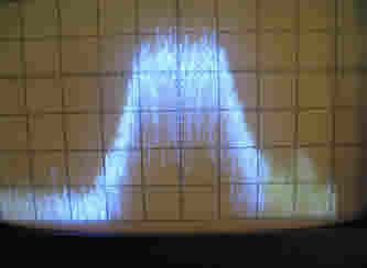
Proper 20 dB amplifier
The Spec Ana is set for 20 MHz per division and centered on 1420 MHz. The peak is 30 dB above the floor.
A better way - I finally found a better way to do it without the amplifier at all then using the new setup I solved the problem I was working on so I can set the amplifier aside for another twenty years. Never worry about what you can put off for twenty years when you are an old guy like me.
204. 2010-06-10 Noise Source Information
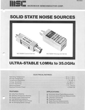
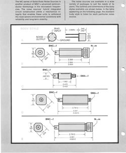
I am getting setup to build the Total Power Receiver and needed some information on the noise source I am using. It is a Microwave Semiconductor mc50018 and I keep loosing the specs. for it. For the last time here it is:'
 |
 |
A good tutorial on noise measurement by Paul Wade (N1BWT) is here...
203. 2010-06-10 Control Panel Problem Solved
(I hope). Still don't know what the problem actually is but a brand new 4 core AMD processor backed up by 8 Gig of memory and a PCI Express video card seemed to solve it. Lets hope. The server is running and open for control. Test scan of the WOW area worked fine.
202. 2010-06-09 Control Panel Problem Again
I decided I would build a new computer for the Remote SETI machine. I did this to solve the 'out of resources' fault I have been unable to find in the software. The new machine is a 4 core AMD machine with 8 Gig of memory so it should solve the problem (its a mirror image of my development machine that doesn't have the problem). I had it running fine but then when I attempted to upgrade the video card to a PCI Express version the whole thing blew up. So far I have replaced the power supply (now 850 watts) the mother board and the video card. If I can't get it running tonight I guess I'll have to take the processor back for an exchange.
I live but I live right between two Fry's stores and spend most of my
time traveling between the two. This is both a blessing and a
curse depending on the traffic jam going on at the time.
I picked up the Analog Devices AD8314 evaluation kit today so I can start on the receiver. The kit comes in a nice little board with SMA connectors all ready to go:

201. 2010-06-02 Control Panel Blow Out
I have been tracking down a software bug in the Control Panel that causes it to blow chunks ever 12-15 hours. Its a tough one to find. It only occurs when the CP is being used via UltraVNC and must be fixed. It might take a while
200. 2010-06-01 Start on Total Power Receiver
With large amounts of advice from people on the SARA list I have made a decision on how to proceed on the SETI Net RA Total Power Receiver. As you may remember if you follow this blog (Item 199 here) I have been trying to build a simple total power receiver as a first step in moving the station to a dual use SETI and RA learning tool.
All the advice emphasized the importance of temperature stability and the small signals I am attempting to discover.
The choice came down to building a Square Law or a Log receiver. A good example of a Square Law receiver detector is this:
This is the one in use by Malcolm Mallette at the University of Indianapolis on their five meter dish. Bruce Randall added the following comments to this design:
| To
all. I would be inclined to use the U Indy detector http://radio.uindy.edu/det.gif with some modernization. This circuit was developed in 1997, and better parts are available. Note that the zero point is temperature compensated, the gain is not. Build it in a thermal isolating Styrofoam box. Sudden temperature changes will run you crazy while very gradual changes are not too much of a problem. 1. Change the + power supply from +12V to +8V to allow modern op amps that require lower voltage. 2. The original LF356 was good in its day. I would use a dual op amp. One of the following would be good & 2 amps cost about $2 LMC6482 TLC277 TLC2272 3. 1N34 diodes are not real well matched from part to part. Schottky diodes are better. Glass case diodes MUST be kept in the dark, as the slightest bit of light hitting the diode junction will make a large output change! A 1N6263 or SD101 small signal Schottky diode would be good. Two diodes are a little over $1 for the pair. Note that this circuit biases the diodes so they detect at very low levels. These particular diodes will not work at low levels without bias. 4. Replace the two 510K resistors with 499K 1% so the diode currents match better. My present receiver uses an NE602 square law detector that was in SARA Journal for Oct/Nov/Dec 2007. This uses a chopping scheme to eliminate offset errors. It is more complicated then most will want to build. The U Indy design should work quite well with a lot less parts. On log detectors, I consider the lack of ability to easily calibrate from injected noise at the antenna a set back. For monitoring solar flares where very large signal can be involved, a log detector is the only way to go. If the rest of the receiver is done correctly, a 60dB range log detector could handle signals 1 million time the receiver noise base line! Bruce Randall |
The Log Amp as suggested by Marcus Leech of Shirleys Bay Radio Astronomy Consortium is based on an Analog Device AD8314 Logarithmic Detector:
Functional Block Diagram for AD8314
The advantage to this design is that the detector is on a single device and does have a good range (-45dBm to 0 dBm) and operates at my systems base band of 1420 MHz. The square law detector has a much lower operating point and I would need a down converter to use it.
So I made the decision to build the Log Detector and ordered three AD8314 and an evaluation board with a forth on it. I have received the three and am waiting for the board to be shipped from the Philippines.
The board schematic is here:

This prebuilt board will help me get past the fat finger stage of development on this system. Then I have to build some sort of relay switch so that the RA receiver can be switched In/Out of the output of the LNA and also an A-To-D converter and a way to send the data back to the SETI Net control computer.
I also have on order a 30 MHz wide Band Pass Filter from Marcus Leech
The completed Total Power Receiver might look something like this.
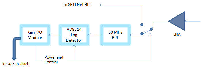
I hope that this simple detector will start SETI Net down the path for Radio Astronomy even though it has shortcomings. The goal is to have a Software Designed Radio (SDR) for the detector is that it has no temperature drift at all and the ability to add advanced detection software.
