V4 Chapter 33
Details
182. 2009-03-12 WOW is Obliterated
Since Sagittarius is up in the morning and its the home of the WOW Signal I thought I would put the system on it for a while. When I tuned the receiver to the WOW frequency 1420,455,600 Hz I saw a huge signal right in the middle of the Spec Ana (100 mVolt) . This thing is *way* stronger than anything I would expect from ET so I have to find the cause of it. To be sure; I moved the antenna around and the signal did get stronger in places but never went away even when I turned the antenna 180° so the signal is local not ET with a Bazillion watt transmitter beaming it right at SETI Net. The signal zero beat frequency is 1420,450,900 with the receiver in SSB mode and drifting.
size="2">I turned off all the equipment in my lab - no change. I shut down my computers - no change. I went around the house and made sure NOTHING was running - no change.
size="2">I have done everything I can do without a scanning receiver to look around the neighborhood. It could be a new cell phone tower that has come on line, a new TV of one of my neighbors, a new bird developed right inside my receiver, who knows.
size="2">I'm going to leave the receiver on the signal and wait to see if it goes away. You can listen to it on the audio/video feed from the front page of this web site.
Found
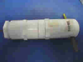
The WOW area bird turned out to be the oscillator in the Kerr PIC IO module (the green board in the lid of the Head End Electronics). Its a 20 MHz crystal that has an overtone right square in the Water Hole and I can see it running every 10 MHz right across the band.
The trouble is that I have three of these modules running; one for Az motor, one for El Motor, and this one that I plan to control a noise source with.
Now what to do???
2009-03-18 - Well the first thing is to base line it.
The Thumbnail (above) shows the huge signal with the LNA connected to the probe normally
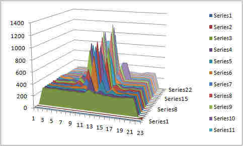
This Thumbnail shows the same signal (gone) when the probe is replaced by a 50 Ω terminator.
This clearly shows that the signal is coming in through the horn probe not generated in either of the two amplifiers.
So now I have this condition.
-
The signal is airborne (above test)
-
When I shut down the LNA power the signal goes away
-
When I shut down power to the three controllers the signal goes away
-
When I shut down all but one controller the signal is still there (any one)
-
The closer to the LNA the stronger the Signal
This seems to be telling me that the signal is radiated from the controller interconnect cable (Cat 5 - 4 twisted pair).
Control & Signal Cable Layout
This cable starts at a RS-2323 to RS-485 converter near my computer. The RS-485 (in the CAT 5 cable) runs about 50 feet to the control box where the first two controllers run the Az and El motors. The cable then runs another 20 feet to the Head End Electronics where a controller runs the BPF in/out relay an A/D converter and a couple of other tasks.
I might try to find some 4 wire twisted pair shielded cable but that would require changing the RG-45 connectors I use now (major pain).
2009-03-25 WELL I GIVE UP
I cannot get rid of the signal. I have tried shielded cable, new PIC controllers, bypass caps., everything I can think of. Nothing changes it much. I do know that it comes direct from my computers. Each computer generates a spike at a slightly different frequency and the spike only goes away when I turn the computer off. That's hard to do by the way because I need the computer to see the spike. It appears that the spike is radiating from the cable going up to the controllers.
I gona give it a rest and work on something else for a while.
181. 2009-03-08 Operating on the receiver
The receiver has a three terminal regulator in it (5 Volt) that drives out the input 'F' connector to power the LNA. I don't want DC going up my co-ax so I have to cut that voltage feed out of the receiver.

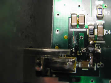
You can see where I scratched the lead that carries the +5V to a very small (about the size of a fly poop) 39 nanoHenry choke. If I want to re-enable it some day I'll look up this web page and say 'ah yes. I remember now' and with a little solder work to bridge that cut it will be back good as new.
Now that the receiver is cleaned up I can connect it directly to the co-ax coming down from the Head End Electronics. To do that I simply Tee it off so that both receivers are looking at the 1420 MHz coming down the pipe. I did a quick scan and it does seem to work. Tomorrow I'll try it on a sun shot that should come out looking like the original I made last October.
size="3">180. 2009-03-07 Characterizing the Radio Astronomy Receiver
size="2">I plan to use the receiver that came with the SRT system as the Radio Astronomy Receiver part of the system. To do that I want to first find a way to baseline its operation. After that I can add it to the system.
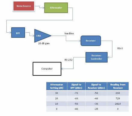
have a noise source that I can use for the base line task. It is a Microwave Semiconductor MC50018 and has a frequency range of 5 MHz to 18 GHz with a flatness of .75 dB and a power requirement of 28 VDC. I also have a HP 436 Power Meter with a HP 8484A power head and a HP step attenuator.

size="2">I then connected the noise source through the attenuator and directly into the Band Pass Filter (BPF) of the SRT receiver.
 I
would have liked to have an attenuator with a finer control but that is
all I have to work with.
I
would have liked to have an attenuator with a finer control but that is
all I have to work with.
It looks like the receiver is swamped somewhere above -25 dBm and likes to operate somewhere about -30 dBm max.