V2 Chapter 17
2005-10-04 to 2005-05. Work on the LNA and a new schematic; Frequency list of known beacons; Testing of the new Icom R7000 receivers with help from Ed Cole
Additional Content
73. New Receiver (2005 -10-01 to 2005-10-05) - I picked up a ICOM IC-R7000 receiver from EBay and it has been delivered.
Now I am attempting to get it running in the system.
| Type: | HF/VHF/UHF receiver/scanner |
| Frequency range: | 25-2000 MHz (Gap between 1000-1025 MHz) |
| Mode: | AM/FM/WFM/SSB |
2005-10-05 Edward Cole gave me a roadmap of tests to make on the system. I'll follow through it and show the results here.
| Step | Results | |||||||||||||||||||||
| 1- test the IC-7000 with the WSS. To get a weak signal this will require the use of a coaxial attenuator or separating the WSS from the receiver as follows |  The output of the WSS, low position
is -29.75 dBm, Hi position is -5.3 dBm as measure with this setup.
I have modified the WSS so that I can switch in or out the last two
stages of the oscillator amps. The output of the WSS, low position
is -29.75 dBm, Hi position is -5.3 dBm as measure with this setup.
I have modified the WSS so that I can switch in or out the last two
stages of the oscillator amps. |
|||||||||||||||||||||
| 1a: The receiver probably has a sensitivity of about
1-uV (-107 dBm) to 2-uV (-101 dBm). You stated your WSS outputs about -6
dBM so you need to add about 100 dB of attenuation to produce a -106 dBm
signal for the IC-7000. I have a 0-100 dB step attenuator that I use that
is calibrated to 1000 MHz (close enough), |
By running the output of the WSS through my HP 8495B attenuator I measure -64.76 dBm in the 30 dB position. The 8484 power sensor runs out of
I should get the following in the other positions:
|
|||||||||||||||||||||
| 2- connect and test the coax line the same way you just tested the receiver (use the receiver s-meter to observe differences in signal level...I would expect a drop in one s-unit (3dB) per 40-foot of coax cable) | I couldn't extract the run of co-ax in
use, its inside a PVC pipe so I substituted a 30' piece of RG-8.
This has BNCs on both ends to which I added BNC to SMA one end and BNC to
"N" on the other. The measured loss is 9.51 dB. I
connected the whole thing to the receiver and found:
|
|||||||||||||||||||||
| 3- add the line amp to the coax line and test (you
should see a rise in signal) |
 The
red flexible hardline goes into the line amp from the attenuator string.
The output of the Line amp goes to the receiver. This gives me the
following results. Things are getting pretty 'adapter-ish' now... The
red flexible hardline goes into the line amp from the attenuator string.
The output of the Line amp goes to the receiver. This gives me the
following results. Things are getting pretty 'adapter-ish' now...
|
|||||||||||||||||||||
| 4 and 5- add the coax relay (in bypass) which should not affect the signal hardly at all | Filter in line - Attn. 50 dB full
quieting, S Meter at 3.5 (one S unit lower)
Filter bypassed - Attn. 5 0 dB, S Meter at 5 Looks like the filter adds about 1 S Unit of insertion loss. |
|||||||||||||||||||||
| 6- add the LNA and you should see a huge increase in signal (several s-units) | Attn at 70 db - full quieting, S Meter at 7. This is a
calculated signal level inserted into the LNA of 130.86 (attenuator string)
+ 9.51 dB from the RG-8 = -140 dBm. Seems to be working.
For an additional test I added 30 dB more to the attenuator string and at with the attenuator set at 50 dB I got about 50% quieting and a S Meter reading of 5. |
|||||||||||||||||||||
| 7- attach LNA to feed horn and place WSS in front of feed horn (this should equal or see more signal than step 6) | Just pointing the feed horn toward the WSS quiets the receiver with the attenuator set at 70 dB and the additional 30 dB attenuator in the string. S Meter at 7.5 Seems to work. | |||||||||||||||||||||
| 8- hold WSS in front of dish with compete system
connected (should see an increase over step 7) note if you do not see this it may indicate that your feed horn is not working well or that its placement in front of the dish is not correct (centered and at the focal point) |
I mounted the horn back on the LNA and tuned to 1575.42 and
then moved the dish around to Az 221.25 and El 36 degrees and there was the
satellite.
Loud and clear. |
This finishes the problem hunt but I'm not really sure what solved it. It could have been the electrical connection between the horn and the LNA; it could have been a loose connector (somewhere) or it could have been simply not pointing the antenna in the right direction.
2005-10-04 The problems started when I attempted to find a beacon with the receiver. I got on the SETI League Argus mail list and ask the question:
| Me | Response |
| What is the freq of any GPS sat or any other beacon that I could use? | FN20ut (Tom) - GPS > 1575.42 Mhz / Other common
satellite frequency> 1544.50 Mhz
David Ocame - 1575.42 MHz Dr. Shuch - Also, somewhat weaker GPS L2 signals at 1227.6 MHz;
geostationary WEFAX Jo89sn (Greg ) L1 1575.42MHz |
Trouble shooting steps:
- I can't hear any of the birds that have been pointed out. I do hear a signal at 1379.913 that Greg said was the L4 carrier but it is very weak and although I can move the antenna and it disappears I have to move it about 20 degrees in either Az or El before it goes away. Doesn't seem right to me.
- I pulled the LO, filter and line amp down and tested it on my bench. I ran the Weak Signal Source (WSS) into the Line Amp and it seemed to do its thing kicking the signal up about 12 dB as measured on my HP 141T Spec Ana. That seemed right
- I then just let the WSS run unconnected and could see the LO and line amp pull it out of the mud when powered on. That seemed right.
- Switching the filter in or out doesn't change the signal and that seems right as well.
- When I put the LO assembly back in the prime focus it still seems to work but I still can't hear any of the birds (other then 1379.913).
2005-10- 01- Receiver powered up fine and seems to work. As I had heard the internal power supply in this unit runs *very* hot, so hot that you cannot touch the rear of the unit, and should be replaced with an external unit. This was done by replacing a rear panel Molex jumper with a run of heavy gauge wire down to my Astron 12 VDC supply.
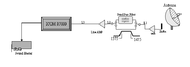
2005-10-03 - Connecting the receiver to the system was simple. This is the setup:
 |
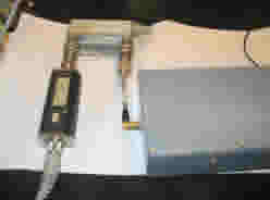
The following picture is of the sealed box with the electronics at the
prime focus of the antenna 
Left to Right:
LNA - Band Pass Filter - Line Amp is actually:
 range
below this so I have to depend on the attenuator itself for the rest.
With only the attenuator I can get down to -104.76 dB so I had to add an
additional 10 dB attenuator using a Midwest Microwave 263 attenuator.